The Photographic Dome
The New Dome, erected by members of the Society during the summer of 2008, starting in April, at the end of Austerfield’s field, adjacent to the Old Dome.
The Observatory Log reports details of the work as it was done.
It’s a 3.5 Metre GRP dome by Sirius of Australia, on a 4.5 Metre square base of 8″ thick concrete. It’s mains powered from the old dome which is powered from the main building by an underground cable.
There is also a data line connection from the new to the main building via the old dome, enabling it to send data, or be controlled from the main building or from the internet. This includes the telescopes and cameras in it too, of course.
The new dome’s work will be primarily, though not exclusively, astrophotography, leaving the old to handle visual work.
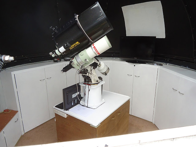
There is an insulated and carpeted floor inside taking the feet of the photographers 7″ above the concrete, and in the centre is a 10″ dia. steel pier, with a 600mm square base, bolted to the concrete. A 900GTO Astro Physics mount sits on top of the pier, and carries an Orion Optics ODK12 telescope. Its 12″ aperture has a focal length of 2040mm (f/6.8) for medium to long focal length work on planetary nebulae, asteroids, planets, doubles etc., and a Takahashi FSQ106ED refractor for wide field work, nebulae, star fields etc.
This drawing shows the storage space built into the dome walls during the Autumn of 2015. The cupboards form a full circle of storage space 4′ high and 15″ deep, and is for storage of spare telescopes, loan-out telescopes, show equipment like the gazebo, and all the society’s equipment currently being held in members’ homes, and the society’s Library too. There is also storage in the cupboard under the central pier, where mostly eyepieces, extension tubes, the PC, batteries etc., items directly related to the telescopes above are housed.
Solar work is done with the Solar Spectrum system on the Sky-Watcher 80ED in the old dome. Fitted to the Skywatcher 80ED it will be available for field work, schools, shows etc.
Though the society will continue to use the telescopes from within the dome, we are preparing the system for remote use, to which end we have a PC and all relevant equipment located under the mount.
We also plan to use the equipment to make webcasts of solar activity, to be available for local schools, and Lunar and planetary activity during early evenings, for members and the general public.
Stored in the big dome cupboards are the PST and SolarMax70 solar telescopes.
Instructions on Setting Up and Running the System.
A. After opening the door, reach to the bottom left for the light switches, the white one for white light, the red one for the red lights. The red one powers the ring of LED bulbs round the dome wall, these can be changed to various colours though mainly used as red.
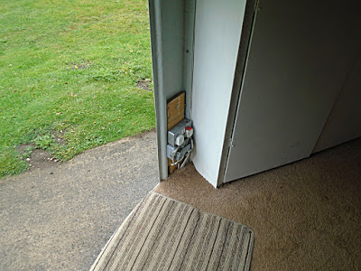
DO NOT TOUCH the covered switches below them, these are likely to turn all power off to both domes, and will require reconnection in the nearby classroom.
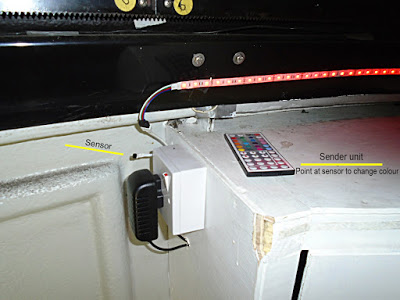
Though the white switch operates the white lights directly, the red operates through a secondary system. Current is sent to a ring of LED lights round the dome wall via a secondary system. This allows for the LEDs to be changed through a var1ty of colours controlled by a hand held ‘TV like’ device. Point it at the sensor and press the chosen colour button to change the colour. The most often used colours are red and white.
B. Remove the dust cover and store it on the wall seat.
C. There are 8 switches to operate to start the system.
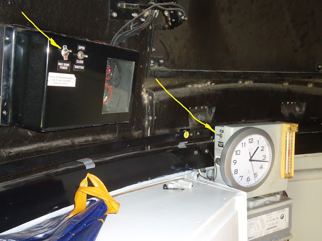
1. the Dome Rotation. On the box on the SW wall of the dome.
2. the Dome Shutter. On the rotating part of the dome at the bottom left of the shutter.
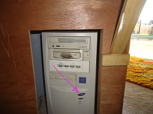
3. the Computer, the switch is on the front of the PC, which is under the central cupboard as seen from the west.
4. the Computer Screen, on the front of the screen.
5. the Power to the mount. On the south face of the mount. There is no actual switch, but a round plug to be pushed into a round socket. There is a telltale light that must light up RED to indicate it is connected, if this is yellow, it means NOT connected. Pull out and try again. If it persists in showing a yellow light, you must use a penknife to very slightly open the central pin connection in the plug, re-insert the plug. That means VERY SLIGHTLY. VERY SLIGHTLY means VERY SLIGHTLY!
6. the Serial plug to the left of the Power switch, on the south face of the mount. Push it into the upper of the two sockets, the right way up of course.
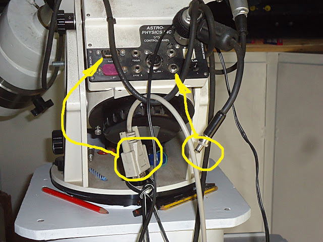
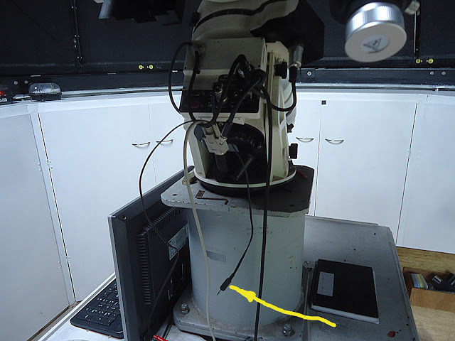
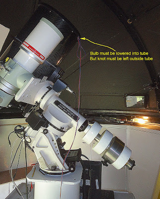
7. The power plug for the cooling fans must be plugged into the socket in the rear face of the ODK, below the focuser. The cable should be found hanging from the same loop as the serial plug is, as shown by the yellow arrow, then plugged into the socket under the focuser on the base plate of the ODK. You should hear the quiet hum of the 3 fans. These will help cool the primary and keep moisture off the primary.
8. As a means of keeping moisture off the optics we use a heater in the form of a 1.5w/12vdc bulb lowered into the tube on the end of a length of cable. This must be withdrawn, the bulb removed (this acts as a switch) and set aside under the mount. The cable has a prominent knot in it’s length at 22″ from the bulb to ensure you don’t lower it too deeply into the tube and touch the primary.
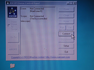
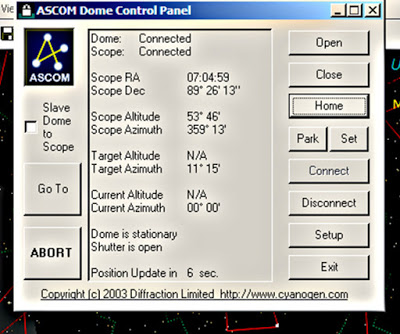
D. Wait for the PC to start up and display the Ascom Dome Control panel. This will take a few minutes. Then click the “Connect” button on the panel, and wait for the PC to process these commands, which will end when TheSky software screens a part of the sky that the telescope is pointing at, and the dome has rotated to its Home position, the north. The Dome Control panel will now be hidden by the TheSky software so you will have to highlight it to bring it to the front.
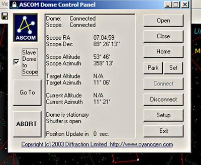
E. On the Dome Control panel click the small square labelled “Slave”, and the dome should rotate to where the telescope is pointing. In most cases it will therefore not move much as the normal home position for the telescope is pointing to the north too.
F. She is now ready for action.
This instrument is not as simple as the Meade in the smaller dome. That telescope sits on top of a fork mount and cannot run into the pier, or do itself damage, though it can get “lost”.
This is a German Equatorial Mount and consists of the telescope on one side of the mount, counterbalanced by the counterweights on the other, and either can run into the support system. So it is good common sense, when sending her to a target, that you watch carefully, with a finger covering the STOP button. This is on the handset in the middle of the Direction buttons. When sending her to various locations it is also good sense to keep an eye on any camera cables you have added to the system to ensure they don’t snag anything.
A requirement of GE mounts is that the telescope must be square to the mount on both sides, but I haven’t completed that yet, so she is slightly different when on one side of the mount to when she’s on the other. This means for instance, that when moving from target to target with the telescope on the east of the mount, she points very well, but will be slightly out when asked to point to a target that requires her to move from the east to west of the mount. It may then be necessary to re-calibrate her to a nearby star that you know, on the new side of the mount, before exploring thas side of the mount. From then she will perform well till asked to move to the other side of the mount when she’ll need “re-calibration”. This is equivalent to “Sync” on the Meade in the other dome. All this will end when I get round to matching both sides up to each other. But it involves testing and shimming the telescope tube and is a long job.
A feature of GE mounts, that affects astrophotographers only, is that the camera will be turned upside-down when the telescope is moved to the other side of the mount. But this mount was chosen because it has the ability to track past the meridian for up to 6 hours, and it will allow you to take it well past the meridian if you do it with the handset, but will not if you “send” it there with TheSky software.
To Re-Calibrate, centralise a KNOWN and RECOGNISED (make sure you do recognise it) star in the eyepiece, using the handset. You may have to change the drive speed to be able to do this accurately. Ensure the chosen star is actually the one in the dialogue box, then click the “Telescope” button on the top row of the dialogue box. This will give you access to the “Re-Cal” button and the “Sync” button. Click on the “Re-Cal”button, and NOT on the “SYNC” button. Take great care on this point, DO NOT USE THE SYNC. BUTTON.
If you press the SYNC button, the mount will be expecting to be sent to a star on the mount’s own internal list of stars, but if it is sent to a location not on this internal list, it will be thrown into disarray, and will have to be turned off and re-started.
Speed changing is done on the handset, by repeatedly pressing the “6” key, after pressing the Menu key, till a suitable speed is seen on the handset screen. Similarly the “8” key controls the tracking speed.)
She is now ready to work on this side of the mount.
The controlling of the telescope is done through TheSky software, on the PC. By clicking on a chosen target on the screen, a dialogue box is screened. Check that the dialogue box refers to the chosen target, click on the SMALL GREEN TELESCOPE ICON at the bottom of the box. Have your finger ready near the handset’s STOP button, in case the telescopes or counterweights get too close to the mount, or the camera cables get close to snagging.
Provided the main screen is high-lighted blue as being in operation and the dialogue box isn’t high-lighted blue, the scale of the star chart on the screen is controlled by the PgUp and PgDnkeys on the keyboard, or the small “+” and “-” on the edge of the software screen, or by the roller on the mouse.
You can control the system by either the PC or the handset, but it is sensible to use one or the other but not both when sending her to targets. Better in all respects to use the PC, with the occasional Re-Calibrate with the handset.
Some notes on using TheSky6 software.
This is the full screen, easier on the eye in the dark but without icons, it can be interchanged with the normal screen version with the space bar.
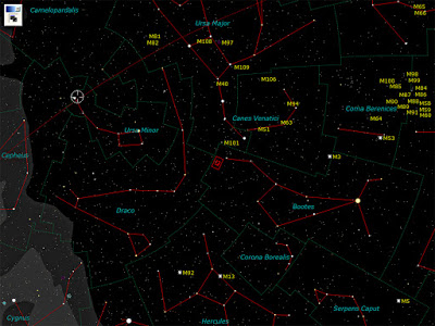
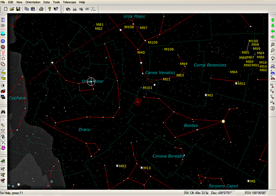
The icons on the right are mostly on directions, whereas those on the left are for what’s shown on screen. There should be little reason for using them except for the yellow telescope near the bottom. This adds or removes the white crossed-ring seen on Ursa Minor. If it is on screen, the software will not allow you to move to any other part of the sky. Clicking the yellow telescope at the bottom left of the screen removes it and allow you to move freely around the sky.
The red rectangles in the middle indicate the field of view of particular camera/telescope combinations, which can be changed by accessing the ‘View’ button on the top line.
The focusers. The primary purpose of the equipment in this dome favours astrophotography and an important part of that is focusing the cameras. The weight of the camera can be quite large so control of the focuser’s resistance to slipage is important.
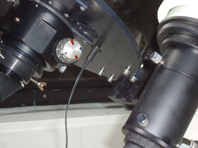
The ODK focuser’s resistance to slipage is controlled by the 3 Allen screws on the underside, 2 smaller ones and a large central one. Don’t make these too tight or you’ll lose all feel of the focusing. The larger thumb screw is a lock, there is another on the top face of the focuser.
For the Tak, the control of the focuser is vested in the small lever near the middle of the focuser. Again don’t tighten this too much or all feel is lost. It is currently set correctly, so don’t touch it.
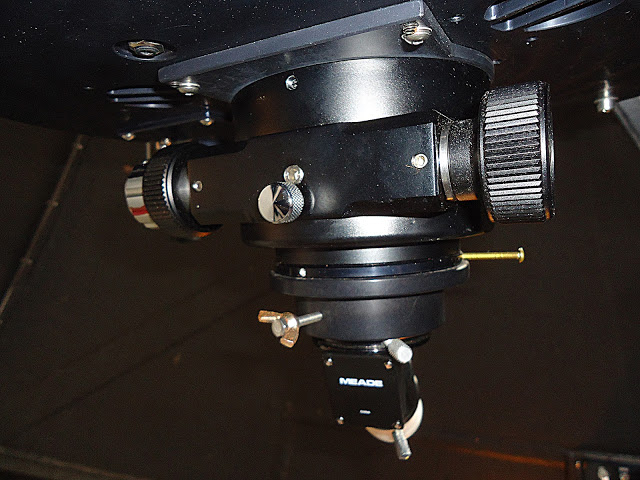
Underside view of the ODK focuser
Closing down.
Click the “X” at the top right of TheSky software screen. This will throw up a dialogue box reminding you that the telescope isn’t parked, and do you want to Park it. Click Yes and it will be done. A second box will screen asking if you want to save things. No you don’t want to save. The planetarium software will close down, leaving the Ascom Dome Control panel on screen. Click on the “Close” button and the “Park” button. When they’ve done, click on the “Exit” button. It will ask if you realise that the telescope will be disconnected. To which you respond, “Yes, I know, do as you’re told”, or words to that effect.
Then Turn off the 8 switches you switched on at the start, ie.
Dome Shutter,
Dome Rotation,
Computer, using the Start button on the screen,
Screen, the telescope’s
Fans and the mount’s
Power and
Serial Connector.
Lower the tube heater into the telescope’s tube above the vane holding the secondary (not as shown below) up to the knot in the cable. Reconnect it to the supply, ensure its little, red light is on and then replace the tube cover.
Ensure all the eyepieces and other items have been returned to their correct storage places, so you can find them next time you use the system. Fit the covers on both telescopes and the finder, at both ends.
Cover the telescopes with the dust cover, recheck that all 8 switches are off, turn out the lights and lock up.
All the above is basic and will work well, but, and there’s always a “but”, if you make a mistake in anything, it will be thrown off course and may not do what you want from then onwards. The correction is usually easy enough, but requires more knowledge, and this is obtainable through practice. So come down and practice.
The fall-back solution to all problems is to turn off, correctly if you can, then re-start.
This situation applies equally to the Meade, though the chance of damage is much less likely there because it has a fork mount.
BJ 1.1.13/BJ 8.2.15/BJ-25.1.16/BJ-17.4.16/BJ-17.9.16/BJ-27.8.17/BJ-9.9.17
Copyright © 2018-21 Doncaster Astronomical Society. Registered Charity No: 1091486